
"Clocking is not a peripheral subsystem in digital audio. It is the temporal infrastructure upon which all conversion depends."
Introduction: When Time Becomes a Signal
Word clock is a single-frequency digital timing reference used for synchronization between digital audio devices. It carries no audio content. Its purpose is to align sampling events across converters and digital systems operating from 44.1 kHz through modern high-rate formats exceeding 384 kHz.
On paper, it appears trivial: a square wave, a fixed frequency, a shared metronome. In practice, it behaves like something far more physical. Because what matters is not frequency, but the edge.
Once transition speeds enter the nanosecond regime, word clock stops behaving like a low-frequency control signal and begins behaving like a high-speed transmission-line system. Impedance, reflections, and connector behavior become part of the timing equation. At that point, digital audio clocking stops being abstract logic and becomes electrical engineering.
Word Clock and Reference Clock: The First Critical Distinction
Before discussing impedance, transmission lines, or jitter mechanisms, it is essential to separate two terms that are often conflated but describe fundamentally different layers of timing architecture.
Word Clock
Word clock is a sample-rate synchronization signal.
- Operates at the audio sample rate (44.1 kHz, 48 kHz, etc.)
- Distributed between devices
- Defines when audio conversion events occur
In practical terms, word clock is the execution layer of timing. It ensures that multiple devices agree on the moment at which sampling happens. It does not define long-term frequency stability. It assumes that stability already exists elsewhere in the system.
Reference Clock (Master Clock, typically 10 MHz)
A reference clock is a frequency standard used to generate or discipline all internal timing domains.
- Typically 10 MHz in audio and RF systems
- Not tied to sample rate
- Used by PLLs and synthesis systems to derive audio clocks
- Defines the stability baseline of the entire timing architecture
If word clock defines when, reference clock defines how stable "when" actually is. It is the underlying timebase from which all derived clocks are constructed.
The Relationship
These operate at different layers: the reference clock defines the quality of time; word clock distributes the application of time. In systems that support external 10 MHz references, word clock becomes a downstream expression of a higher-stability master reference rather than the primary timing source itself.
This distinction is essential. Without it, external clocking appears redundant. With it, it becomes architectural.
Why Word Clock Behaves Like an RF Signal
A common misconception is that low-frequency clocks are electrically slow. They are not. What defines behavior is edge speed.
Fast transitions generate spectral components extending into the tens or hundreds of megahertz. At that point, cables behave as transmission lines. And transmission lines do only one thing: they carry waves, including reflections.
Transmission Lines and Impedance Continuity
A clock signal propagates as an electromagnetic wave. When it encounters an impedance discontinuity, part of that wave is reflected.
Γ = (ZL − Z0) / (ZL + Z0)
Where ZL is the termination impedance and Z0 is the cable impedance. When matched, energy is absorbed cleanly. When mismatched, reflections return and interact with subsequent edges.
The system still locks. But the receiver no longer sees a perfectly clean transition. It sees a slightly perturbed one. That perturbation can shift threshold crossing time. In a clocked system, that shift is jitter. For the broader treatment of why source and load impedance must agree, see Impedance Matching.
Where Timing Becomes Interpretation: The PLL
At the receiving device, word clock is almost never used directly. It is interpreted through a phase-locked loop (PLL). A PLL is not a passive conductor. It is a dynamic control system.
- It tracks low-frequency phase variations
- It suppresses high-frequency noise
- It defines a transfer function for timing error propagation
Meaning the system does not pass clock integrity unchanged. It interprets it. And importantly, it cannot eliminate everything. Some timing noise is tracked. Some is rejected. Some remains.
Phase Noise vs Jitter
Jitter and phase noise describe the same phenomenon in different domains. Jitter is time-domain variation; phase noise is its frequency-domain representation. Phase noise is especially important in audio systems because it reveals close-in instability near the carrier. This is the region most relevant to perceived timing precision, and the region least correctable by downstream PLLs. The role of jitter across the wider digital chain is covered in The Digital Hierarchy.
Internal Clocks vs External Reference Clocks
Every digital audio device already contains a clock, typically a TCXO or PLL-derived oscillator located close to the conversion stage. So why introduce an external reference? Because the system architecture changes.
Instead of independent timing domains per device, multiple devices are disciplined to a shared reference. This creates a unified timing domain. But only if the reference is sufficiently stable to justify replacing internal oscillators as the primary timing anchor. Otherwise, the system distributes uncertainty more precisely.
Why the Quality of the Reference Matters
A PLL does not remove phase noise. It redistributes it. Therefore, the reference oscillator remains fundamental. OCXO designs improve this reference layer by maintaining a constant crystal temperature, reducing drift and close-in phase noise compared to typical TCXO implementations found in most audio devices. This does not change tonal balance. It changes temporal stability.
Why External Clocking Exists at All
External clocking is not an upgrade. It is a shift in architecture. Instead of multiple independent clocks, the system becomes a synchronized timing domain anchored to a shared reference. This only makes sense if that reference is better than the internal alternatives it replaces.
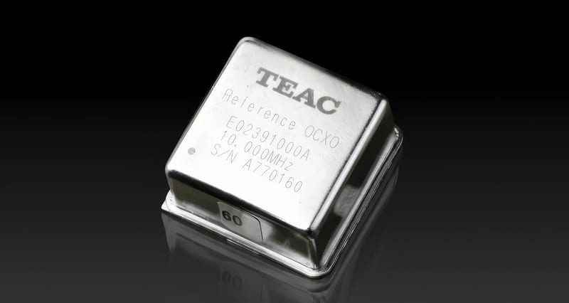
The TEAC CG-10M-X: A Practical OCXO Reference
The TEAC CG-10M-X occupies a specific position in the digital audio hierarchy. It is not a laboratory instrument. It is not a rubidium standard. It does not attempt to be either. Instead, it is a system-oriented OCXO reference generator designed for integration into high-end audio environments.
At its core is an oven-controlled crystal oscillator that stabilizes the quartz element at a constant operating temperature, significantly reducing drift and close-in phase noise compared to typical internal TCXO-based clocks. But its real significance is not absolute performance. It is accessibility.
A Controlled Concession: Where It Sits in the Hierarchy
It would be incorrect to suggest that the CG-10M-X represents the ultimate limit of clocking performance. Rubidium standards and ultra-high-end OCXO systems exist that extend both stability and phase noise performance further still. However, those systems operate in a different domain: higher cost, higher complexity, and rapidly diminishing returns that move beyond conventional audio system design.
The CG-10M-X occupies a more practical position. It is a true OCXO reference implemented at a price where system-level adoption becomes realistic rather than theoretical. In that sense, it sits at a kind of regency point in audio clocking: not the top of the hierarchy, but a stable, serious reference level that moves systems clearly beyond internal TCXO-based timing without entering laboratory infrastructure cost structures. That balance is rare. A meaningful engineering improvement that remains deployable. It is one corner of the wider system examined in The Ultimate Digital Front End?.
System-Level Behavior: UD-701N vs VRDS Transport
Within TEAC's ecosystem, the effect of an external 10 MHz reference is not uniform across components, and this distinction is central to understanding its real-world behavior.
In a device such as the UD-701N, the external 10 MHz reference acts as a timing foundation for internal PLL-based clock generation. However, the DAC architecture still performs significant internal reclocking and isolation. As a result, the external reference primarily shifts the long-term stability baseline rather than directly determining the final conversion clock in a one-to-one manner. In this context, the effect is typically subtle but structurally consistent, influencing spatial stability, low-level coherence, and the perceived organization of complex material rather than producing dramatic tonal changes.
By contrast, a dedicated CD transport such as the VRDS-701T operates under a more exposed clocking condition. It must recover, generate, and transmit a stable digital stream from a mechanically active environment while maintaining strict timing integrity at the output stage. Here, the external 10 MHz reference becomes a primary timing anchor for the output clock generation chain, replacing a locally generated TCXO-based reference with a shared OCXO-based system reference.
As a result, the same master clock can appear more immediately influential in transport applications, not because the DAC is less capable, but because the transport's timing domain is less insulated from real-time mechanical and electronic variability.
- The UD-701N integrates and stabilizes timing internally
- The VRDS transport depends more directly on its outgoing timing reference
Both benefit from a shared master clock, but they reveal that benefit differently.
What Changes in Practice
When a system transitions to a high-quality external OCXO reference, the change is not tonal. It is structural. Commonly reported impressions include:
- greater continuity of low-level detail
- improved stability of spatial positioning
- more natural decay of reverberation
- reduced sense of low-level grain in complex passages
These effects arise from reduced timing uncertainty rather than frequency-domain alteration.
50Ω vs 75Ω Systems
Clock distribution follows two engineering lineages.
75Ω systems
- optimized for low attenuation
- used in broadcast and audio distribution
- typical for word clock and S/PDIF
50Ω systems
- optimized for RF and reference clocking
- used in 10 MHz systems and instrumentation
They are not interchangeable without electrical consequences.
Impedance Mismatch
A 50Ω-75Ω interface produces:
Γ ≈ 0.2
- ~20% voltage reflection
- ~4% power reflection
The significance depends on termination and system design.
BNC Connectors
BNC connectors are part of the transmission line, not passive hardware. 50Ω versions are built for RF robustness; 75Ω versions for impedance continuity. At these edge speeds, geometry becomes part of signal integrity. The same principle governs every connector in the chain, as set out in Connectors.
The VRDS-701T: System-Level Application
In a transport such as the VRDS-701T, the 10 MHz reference input allows the device to derive its output clock from the same OCXO-based timing domain as the DAC. This creates a shared timing architecture rather than independent clock domains. The result is not a change in data. It is a change in temporal coherence across the system.
Outlook: System Architecture Beyond the Component Level
Once a shared reference clock becomes the foundation of a digital audio system, the logical next step is no longer individual component optimization, but system-wide timing architecture. In such a framework, the reference clock is not treated as an accessory to a DAC or transport, but as the central timing authority from which all digital processes derive coherence.
This naturally extends the discussion beyond conventional source components toward complete system structures where conversion, transport, and amplification are treated as a synchronized chain rather than isolated stages. In that context, future system designs may place increasing emphasis on unified reference distribution across digital sources, conversion stages, and active loudspeaker systems, where the final transduction stage is also time-referenced rather than purely signal-fed.
The technical implications of such an approach depend on implementation, but the underlying principle remains consistent: as system-level timing coherence increases, the role of the reference clock shifts from component support function to architectural foundation.
Final Thought
Digital audio is often discussed in terms of formats and bit depth. But at the point of conversion, the determining factor is not data structure. It is timing stability.
Word clock defines synchronization. Reference clock defines stability. Between them lies the architecture of digital time. When properly implemented, the clock ceases to be a variable. It becomes a reference point.
Questions about Word Clock and Reference Clocking
What is the difference between word clock and a reference (master) clock? +
Word clock is a sample-rate synchronization signal (44.1 kHz, 48 kHz, etc.) distributed between devices - it defines WHEN audio conversion events occur. A reference clock, typically 10 MHz, is a frequency standard not tied to sample rate, used by PLLs to derive audio clocks; it defines HOW STABLE that "when" actually is.
Put simply: the reference clock defines the quality of time, while word clock distributes the application of time.
Why does word clock behave like a radio-frequency signal? +
What matters is not the frequency but the edge. Fast transitions generate spectral components extending into the tens or hundreds of megahertz, so at those edge speeds the cable behaves as a transmission line, and transmission lines carry waves including reflections.
When the signal meets an impedance discontinuity, part of it reflects back and perturbs subsequent edges, shifting the threshold-crossing time - and in a clocked system, that shift is jitter.
What happens if you mix 50-ohm and 75-ohm clock connections? +
They are not interchangeable without electrical consequences. A 50Ω-75Ω interface produces a reflection coefficient of about 0.2 - roughly 20% voltage reflection and about 4% power reflection.
75Ω systems are optimized for low attenuation (word clock, S/PDIF); 50Ω systems are optimized for RF and reference clocking (10 MHz, instrumentation). At these edge speeds the BNC connector is part of the transmission line, not passive hardware, so geometry becomes part of signal integrity.
Does an external master clock change tonal balance? +
No. A PLL does not remove phase noise, it redistributes it, so the reference oscillator remains fundamental. An OCXO reference improves temporal stability, not tonal balance.
The change is structural rather than tonal: greater continuity of low-level detail, more stable spatial positioning, more natural reverberation decay, and reduced low-level grain in complex passages - all from reduced timing uncertainty, not frequency-domain alteration.
Does the TEAC CG-10M-X help the UD-701N or the VRDS-701T transport more? +
It tends to be more immediately audible on the transport. The UD-701N performs significant internal reclocking and isolation, so an external 10 MHz reference mainly shifts the long-term stability baseline - a subtle but consistent effect on spatial stability and low-level coherence.
A CD transport like the VRDS-701T has a less insulated timing domain: the external reference becomes a primary anchor for its output clock, replacing a local TCXO, so the same master clock can appear more influential there. Both benefit; they simply reveal it differently.